|
Making a Watch by Hand - Top - Next - Only fools will go… I am taking my first foolish steps in
watch making and thought others might like to see the results of my work and
how I got there. Maybe it will inspire others to try their hand at making
their own watch too. I am just at the beginning. I do not know as I write
this if this watch will ever really work. But even if it doesn't, there is
the adventure of learning, then the next will be a success. My interest is in making watches. Any
interest I have in learning repairs is motivated by my desire to get the
necessary skills for making my own watches. I would like to stress the fact
that I am not a professional watchmaker and have not yet finished the first
year of the BHI correspondence course up 'til now. There are certainly much
better ways of doing things than mine. If so, please let me know. I am
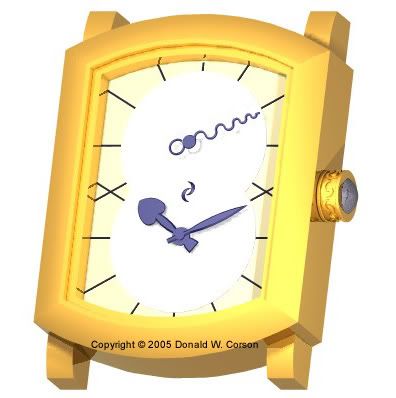
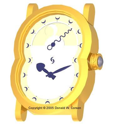
grateful for any aid. This first project is to take the wheels from
a standard calibre, an ETA2824-2, and make the rest of the watch myself to
create a watch like in the images below, in declinations for a mans and a
woman’s watch:
The project started out with much time
studying the 2824, measuring and CAD modeling of all the parts I was planning
on using. You will note that I have moved the seconds from the center as in
the ETA2824 layout to a more northerly position. This causes me to completely
change the wheel placement in the movement and use some 2824 parts more than
once to span the distances, but the plan is not to cut any gears myself for
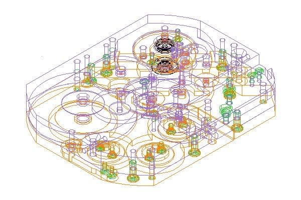
this first project. The plate and bridges look like this in
the CAD:
This is a rendering of the going train,
motion train, keyless works and bridges, without the plate.
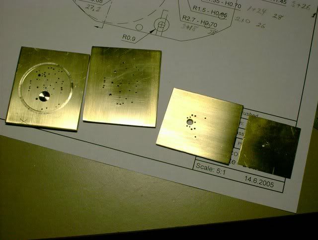
Between the plate, barrel bridge, wheel
bridge, anchor bridge, balance bridge and motion works cover there are only
104 different holes to be drilled in 10 different diameters. To assure some
chance of the thing working I am striving for a positional accuracy of 0.01mm
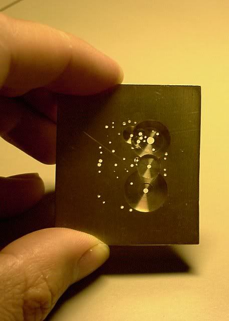
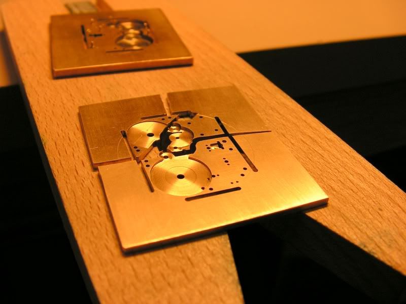
for all holes. Below, you can see the first steps. From
the left, the plate in 2.5mm brass, bridge plate and anchor bridge in 1.5mm
brass and the motion works cover in 0.3mm brass.
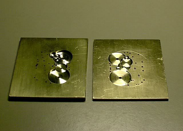
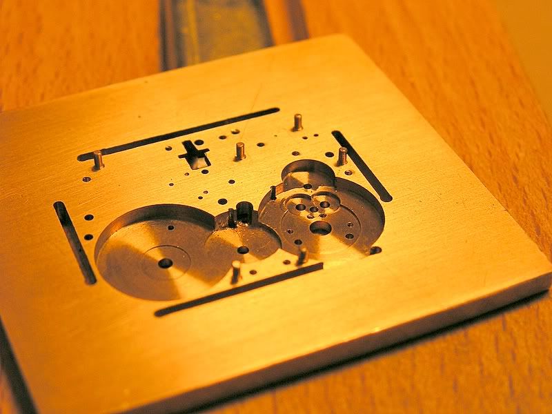
This drilling was followed by turning all
the recesses to depth on the lathe, the non-circular recesses thereafter on a
milling machine. The plan is that the recesses are turned to the level of the
inside face of the jewels when there is no play on the shaft. Adding the
endshake will put each jewel about 0.05mm below the surface. It will be seen
how this assumption holds up in reality later, but it should give me some
small amount of leeway for correction in both directions if necessary.
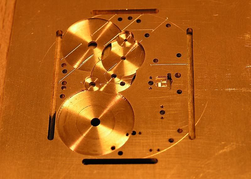
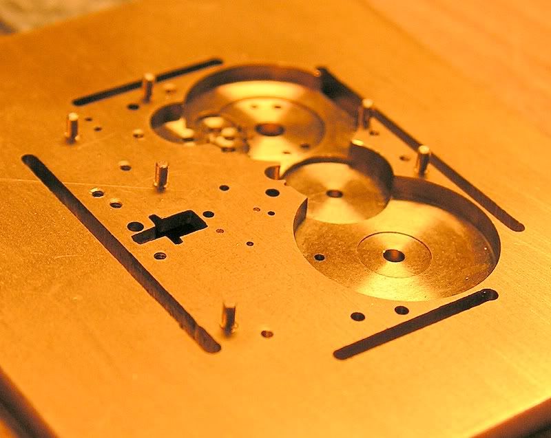
The outside dimension of the movement is
cut out with slots. The excess material left attached to be able to better
hold the pieces for if (when) any further machining is necessary.
You will also notice the markings for
cutting this "bridge" plate to form the barrel bridge, wheel bridge
and balance bridge. In the picture below, the barrel bridge is almost
separate from the rest.
With the bridges separate it is now
necessary to be able to position them accurately. To this end there are two
positioning steady pins mounted on the plate for each bridge.
A first check shows the countersinks for
the screw heads are OK, but some of the steady pins are still too long. I
made countersink tools for the heads of the two screw sizes I am using. These
are the screws from my previous
post on this forum. The tools were made by grinding down the shanks of
broken tungsten steel drills to the correct form. When chucked up in the
lathe they cut very well. I don't think that for this use, for cutting brass,
there is any advantage to that compared to turning them with a graver in
silver steel and then hardening, though. I found it very difficult to get
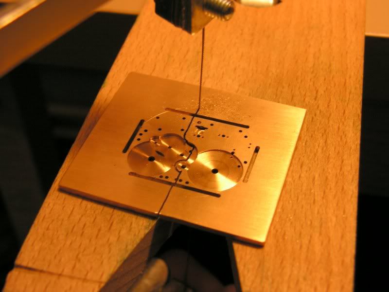
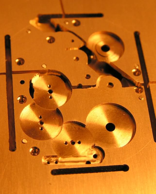
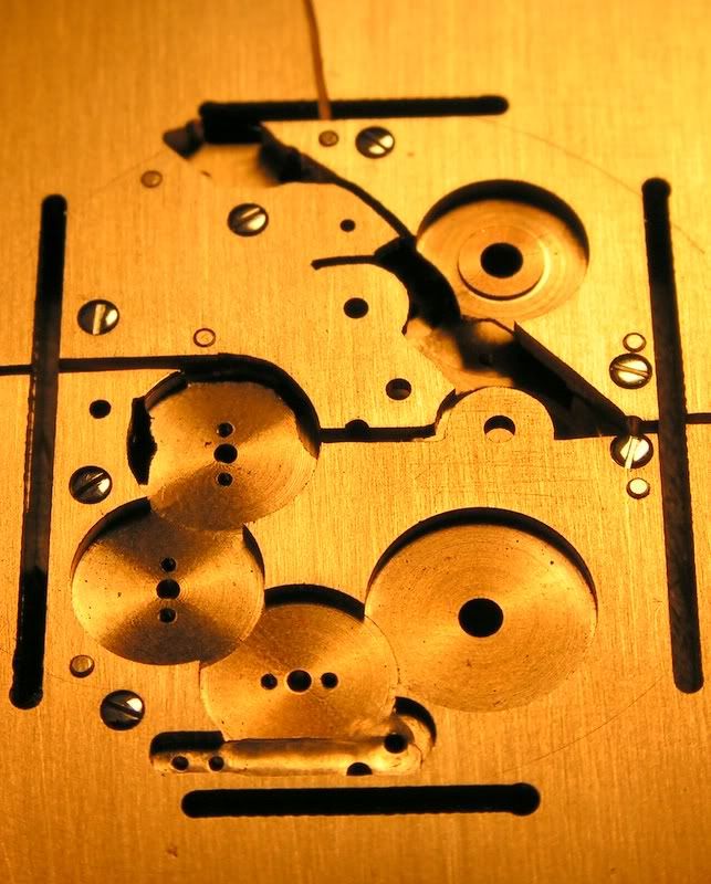
anything like a sharp corner while grinding. In these pictures you can see one of the
effects of using only pre-existing wheels. The placements for the train from
the crown wheel to the ratchet wheel show prominently here. Two extra crown
wheels are used to span the space between the original crown wheel and the
ratchet wheel, while maintaining the proper sense of rotation. This space is
because I placed the barrel to the other side of the movement compared to a
2824.
Things will get more interesting in the
next installment as I place the jewels and hope that the precision of my
measuring and drilling was such that the wheels all fit and turn freely. Still a long, long way to go… Don Copyright © 2005 Donald W. Corson |

If you are in Switzerland, come to a concert of the Orchestre d’Yverdon-les-Bains. Concert schedule on the website.