For the RTTY connector I find also a strange PIN related number from SERVICE MANUAL and MANUAL:
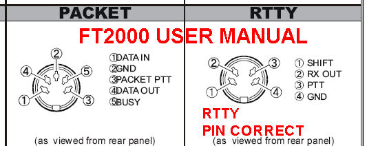
FT2000 MANUAL PAGE 15 and FT2000 MANUAL PAGE 104 for the PIN 1-2-3-4
Then on the SERVICE MANUAL (TECNICAL MANUAL) PAGE 37 MAIN UNITA1 at J1032 (in low to the right).
It is not equal, but while that for AFSK/PACKET J1031 is identical.
RTTY BUS AT MANUAL:
PIN1: SHIFT
PIN2: RTO (RX OUT)
PIN3: PTT
PIN4: GND
RTTY
BUS AT SERVICE MANUAL/TECNICAL MANUAL J1032
PIN1: RTO
PIN2: PTT
PIN3: GND
PIN4: SHIFT
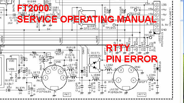
Both in the same position of the connector!!!!
Since the connector PACKET on the TECNICAL MANUAL (service) the PIN are
equal to the MANUAL, on the taking PSK/RTTY PIN there and'
anything that doesn't correctly work.
That there am this difference,very strange? which is that correct?
Then Is the PTT around two takings (PACKET J1031 - RTTY J1032) different?
Don't they work in parallel but are they commanded in the
CPU to choice of the USED MODE key (in this case RTTY key)?
Another very strange thing of the FT2000, that nobody has noticed him?
regard's
Franco, hb9oab
http://www.wlog2000.com